How to Control Deformation in Machining Magnesium Alloy Thick Plates?
A systematic guide addressing warpage after milling magnesium alloy thick plates—covering material condition, residual stress, rough/finish machining sequencing, symmetrical material removal, fixturing, and inspection datum control.
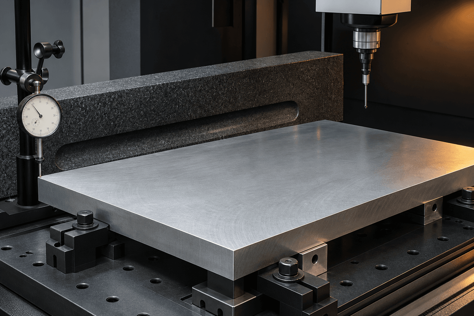
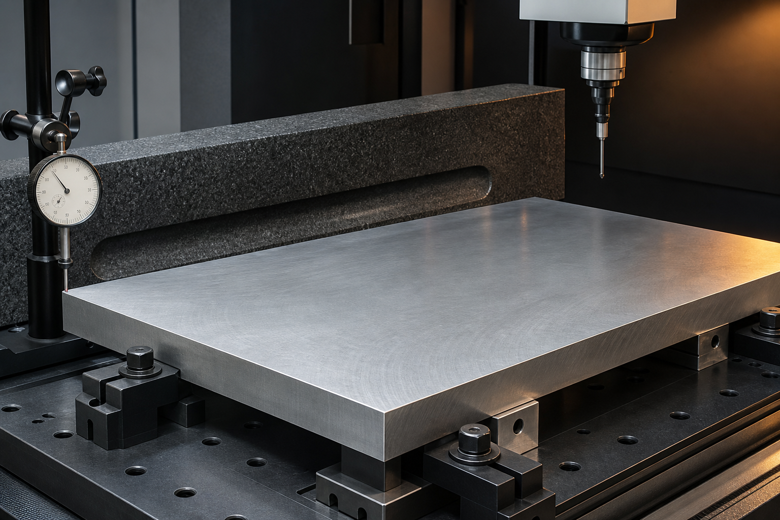
Magnesium alloys are highly machinable—but high cutting speed does not guarantee dimensional stability. Warpage commonly occurs after unclamping, flipping, or even post-surface treatment for thin-walled frames, large-area panels, and parts requiring heavy one-sided material removal. To control deformation, material condition, blank stock allowance, machining sequence, fixturing, and final inspection must be treated as an integrated system.
Where Deformation Typically Originates
Residual Stress Within the Material
Rolling, leveling, heat treatment, and sawing all introduce residual stress. Removing material from one side disrupts the original equilibrium, potentially causing bending or twisting. The larger the thick plate and the higher the material removal ratio, the greater the risk—and the more critical the need for early assessment.
Asymmetric Machining Paths
Removing large amounts of material from one side in a single pass, holding parts rigidly in fixtures for extended durations, or completing rough and finish machining consecutively can cause deformation to concentrate and release upon unclamping.
Temperature and Measurement Conditions
Although magnesium alloys exhibit relatively low cutting resistance, localized temperature rise, tool wear, and poor chip evacuation still affect dimensional accuracy. Measuring immediately after machining versus after full thermal stabilization may yield significantly different results.
A More Robust Process Route
- Confirm blank condition. Specify grade, temper, thickness, tolerances, flatness, and mill certification at order placement—and clarify whether stress-relieving or stabilization is required.
- Provide adequate—but not excessive—stock allowance. Allowance must be tailored to part geometry, material removal ratio, fixture design, and final tolerances—not applied uniformly based on generic experience.
- Establish datums first in rough machining. Machine repeatable datum surfaces and holes before removing bulk material in staged operations.
- Prefer symmetrical material removal. Alternate machining both sides of plate stock to allow gradual stress relief; use multiple light passes for thin-walled structures.
- Schedule unclamping and stabilization time. After rough machining, unclamp, flip, or let parts rest naturally—then re-measure critical datums before proceeding to semi-finish machining.
- Minimize clamping influence in finish machining. Apply only sufficient clamping force to ensure stable positioning—never forcibly flatten already-warped parts and machine them to “fixture-conforming” dimensions.
- Standardize final inspection conditions. Conduct measurements under defined temperature, support configuration, and datum scheme—and explicitly state whether evaluation is performed in free-state or constrained-state.
Three Principles for Fixturing Design
First, support points must align with inspection datums. If parts are flattened differently during machining versus supported differently during inspection, measurement data becomes non-comparable.
Second, clamping force must be repeatable. Document torque values, clamping sequence, and soft-jaw contact positions in work instructions—especially critical for large, thin-walled components.
Third, vacuum chucks, low-melting-point fixtures, or custom supports are not inherently superior. Selection should be based on part rigidity, surface requirements, and production volume—and validated via first-article testing of true post-unclamp shape.
Tooling and Safety Must Not Be Overlooked
Sharp tools, appropriate cutting parameters, and continuous chip evacuation help minimize built-up edge and localized heating. Magnesium chip and dust management must follow dedicated fire-prevention, explosion-proofing, and cleaning protocols—never assume steel or aluminum practices apply. Prior to machining, verify that equipment, dust collection, and fire suppression systems comply with local regulations and facility EHS requirements.
Procurement & Acceptance Checklist
- Blank grade, temper, dimensions, and rolling direction;
- Initial flatness and allowable surface defects;
- Sequence of rough machining, stabilization, semi-finish, and finish machining;
- Datums, measurement temperature, and support method for critical dimensions;
- Flatness, parallelism, and profile after unclamping;
- First-article records, in-process inspections, and batch traceability;
- Whether re-inspection is required before and after surface treatment.
Frequently Asked Questions
Can stress-relief heat treatment eliminate deformation entirely?
No. It may serve as one control measure—but material properties, geometry, material removal strategy, and fixturing collectively determine the outcome.
Does using thicker blanks always improve stability?
Not necessarily. Thicker blanks often require more material removal—and may release greater residual stress. Optimal thickness should be determined through stock allowance analysis and trial machining.
When should trial cuts be conducted?
Trial cuts are recommended for large-size, thin-walled, high-material-removal-ratio, tight-tolerance parts—or when introducing a new material lot for the first time.
Explore available material forms in our Product Center; for evaluation of thick plates, pre-machined blanks, or dimensional acceptance plans, submit part dimensions and critical tolerances via Contact Us.
Sources
ASTM B90/B90M — Magnesium-Alloy Sheet and Plate ASM Handbook, Volume 2 — Properties and Selection: Nonferrous Alloys and Special-Purpose Materials