Magnesium Alloy Extrusion Profile Design Guide: Wall Thickness, Tolerances, Dies & RFQ Checklist
A practical design methodology for magnesium alloy extrusion profiles—from drawings to mass production—covering extrudability assessment, wall thickness transitions, fillets, hollow sections, straightness, twist, and die development.
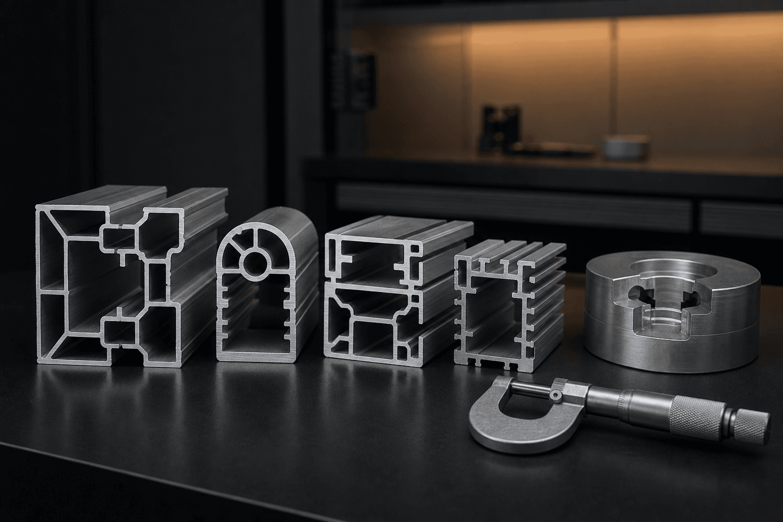
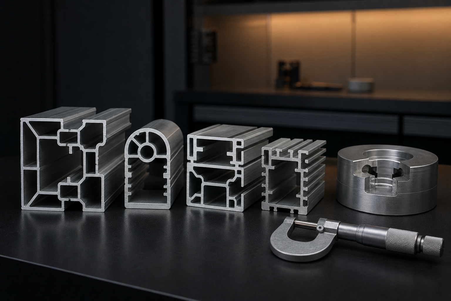
Extrusion enables integration of multiple components, ribs, and mounting features into a single continuous cross-section—making it a key pathway for lightweighting and functional integration in magnesium alloys. However, an optimal profile is not simply an elongated machined part; it must be designed from the outset with metal flow dynamics, die strength, straightening methods, and inspection protocols in mind.
First, Assess Cross-Section Extrudability
Parts suitable for extrusion typically feature a stable cross-section along their length and can achieve final functionality via sawing, drilling, localized milling, and surface finishing. Frequent cross-sectional changes, excessive local features, or tolerances specified solely per precision-machined part requirements will erode extrusion’s cost advantage.
Five Design Factors Affecting Production Stability
1. Maintain Continuous Wall Thickness
Abrupt thickness transitions cause differential metal flow velocities, increasing risks of twist, waviness, and dimensional drift. Where unavoidable, use gradual transitions—and engage your supplier early in die design to assess flow balance.
2. Prefer Fillets Over Sharp Corners
Sharp internal corners increase die stress and hinder metal fill. Appropriately sized fillets improve die life and surface quality—but optimal radii depend on cross-section dimensions, alloy grade, and process parameters.
3. Review Hollow Sections & Tongue Ratios
Hollow or semi-hollow profiles deliver high structural efficiency—but require validation of porthole weld integrity, mandrel rigidity, and die longevity. Do not omit internal manufacturability considerations during quoting—provide full internal geometry, not just external contours.
4. Apply Functional Tolerance Grading
Specifying tight tolerances across all dimensions significantly increases die correction, straightening, and inspection costs. Categorize dimensions as: (a) assembly-critical, (b) secondary machining datums, or (c) non-critical—clearly indicating inspection locations for each.
5. Geometric Deviations Extend Beyond Length Tolerance
Straightness, twist, flatness, angularity, and cross-sectional contour deviations all impact assembly fit. Specify measurement length, support method, and allowable limits on drawings—otherwise, quotations from different suppliers are not comparable.
How Alloy Grade & Temper Influence Design
AZ31B is commonly selected for extrusion projects requiring balanced formability, weldability, and general strength; AZ61A becomes viable when higher strength is prioritized. Stronger grades do not inherently enable more complex thin-wall profiles. Final selection must jointly consider cross-section complexity, extrusion ratio, supplied temper, downstream joining methods, and surface protection requirements.
Four Stages: From Drawing to Mass Production
- Manufacturability Review: Provide 2D cross-section, 3D model, material grade, length, quantity, and service environment—your supplier will feedback minimum feasible wall thickness, fillet radius, and tolerance capability.
- Die Fabrication & Trial Extrusion: Define die ownership, number of die revisions, sample length, dimensional reporting format, and acceptance criteria.
- First-Article Verification: Measure not only one cross-section—but also head, mid, tail, and samples from multiple extrusion heats—to capture dimensional and geometric variation.
- Production Control: Agree on die wear evaluation criteria, in-process sampling frequency, batch traceability, and non-conformance escalation procedures.
What a Complete RFQ Must Include
- Alloy grade and delivery temper;
- 2D drawing with datums and critical-feature callouts;
- 3D model with editable regions clearly marked;
- Single-piece length, cutting method, and annual volume;
- Surface finish, protective film, and packaging specifications;
- Downstream machining, welding, or coating requirements;
- Straightness, twist, and cross-sectional inspection methodology;
- First-article, trial-part, and production documentation requirements;
- Die investment cost, expected lifespan, ownership, and spare-die strategy.
Frequently Asked Questions
Should I simulate first—or machine the die?
For complex, thin-wall, or hollow profiles, conduct manufacturability analysis first—supplemented by flow simulation where needed. Even simple profiles require formal supplier review before die fabrication.
Can extruded profiles meet machined-part tolerances?
Extrusion tolerances and machining tolerances belong to distinct systems. Critical mating surfaces should retain stock for post-extrusion machining.
How to minimize repeated die modifications?
Freeze functional datums, tolerance priority tiers, and inspection methodology before die fabrication—and obtain joint sign-off from design, procurement, quality, and supplier teams.
If you have a new profile design, submit your drawings and annual volume via Contact Us; we’ll evaluate extrudability and downstream processing options based on our material capabilities in the Product Center.
Sources
ASTM B107/B107M — Magnesium-Alloy Extruded Bars, Rods, Profiles, Tubes, and Wire ASM Specialty Handbook — Magnesium and Magnesium Alloys