How to Ensure Surface Integrity in Precision Machining of Magnesium Alloys: Tooling, Burrs, and Inspection
Explains surface integrity control in precision magnesium alloy machining—covering tool geometry, cutting heat, chip evacuation, workholding, burrs, surface scratching, and residual stress—and links these to safety and coating performance.
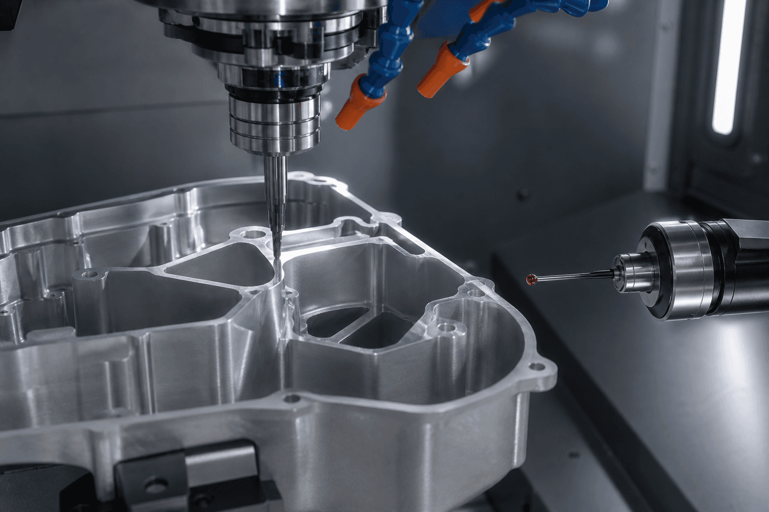
Magnesium alloys exhibit low cutting resistance, but ‘easy machinability’ does not equate to consistent functional surface quality. Tool wear, built-up edge, thin-wall vibration, burrs, localized heating, and cleaning residue all affect sealing performance, fatigue life, coating adhesion, and dimensional stability. Precision machining must concurrently manage geometric accuracy and surface integrity.
What Constitutes Surface Integrity?
Beyond surface roughness, attention must be paid to scratches, tears, folds, burrs, micro-cracks, burn marks/discoloration, residual stress, subsurface deformation, and embedded foreign particles. For sealing surfaces, adhesive bonding areas, and fatigue-critical zones, the significance of each defect varies—drawing specifications should define requirements by zone.
Core Variables Defining the Process Window
| Variable | Impact Direction |
|---|---|
| Tool Material & Sharpness | Dull tools increase heat generation, built-up edge, and burr formation |
| Rake Angle, Clearance Angle & Cutting Edge Geometry | Determine cutting forces, chip evacuation, and edge quality |
| Cutting Speed, Feed Rate & Depth of Cut | Jointly influence thermal load, vibration, and surface texture |
| Workholding & Machining Sequence | Affect thin-wall distortion and residual stress relaxation |
| Chip Evacuation & Cooling Method | Influence built-up edge, temperature rise, and safety |
Parameters must be validated in context—considering machine capability, tool diameter, wall thickness, and specific operation—not copied from generic ‘optimal’ settings.
How to Troubleshoot Burrs and Surface Scratching
First determine whether defects recur consistently with tool path, tool life, or material grain direction; then inspect for chipped edges, built-up edge, tool runout, entry/exit paths, and thin-wall support rigidity. Adding a dedicated deburring step alone increases dimensional variation and may convert sharp burrs into folded edges or embedded particles.
Safety Control Is Integral to the Process
Magnesium chips and fine powder must be collected separately from other metals and managed per particle size, moisture content, and local safety regulations. Dust extraction, equipment cleaning, fire suppression media, and protocols for abnormal heating must undergo EHS assessment. This article does not replace site-specific safety procedures; refer to our dedicated Magnesium Dust Safety topic for further guidance.
Acceptance Recommendations
- Zoned functional surfaces with specified roughness and allowable texture direction;
- Burr height, chamfer, and edge rounding requirements;
- Tool life limits, first/last-piece inspection, and sampling after tool changes;
- Post-cleaning standards for ionic, particulate, or organic residues;
- Surface energy or cleanliness verification prior to coating/adhesive bonding;
- Microscopic, profilometric, or residual stress analysis where critical surfaces are involved.
Must Magnesium Alloys Be Dry-Machined?
Not universally. Dry, minimum quantity lubrication (MQL), or wet machining solutions must be selected based on equipment safety, chip removal efficiency, fluid compatibility, post-machining cleaning requirements, and quality validation.
For tailored optimization of magnesium component surface quality and inspection protocols, submit your material grade, toolpaths, and functional surface requirements via Contact Us; see Products for magnesium alloy bars and plates.
Sources
ASM Handbook, Volume 16 — Machining NFPA 484 — Combustible Metals