How to Diagnose Magnesium Alloy Die-Casting Defects: A Guide to Porosity, Cold Shuts, Shrinkage Cavities, Hot Tears, and Flash
Distinguish porosity, cold shuts, shrinkage cavities, hot tears, and flash in magnesium alloy die-casting by integrating defect morphology, location, cross-section evidence, and process data—and follow a systematic diagnostic pathway covering mold flow, vacuum, temperature control, and release standards.
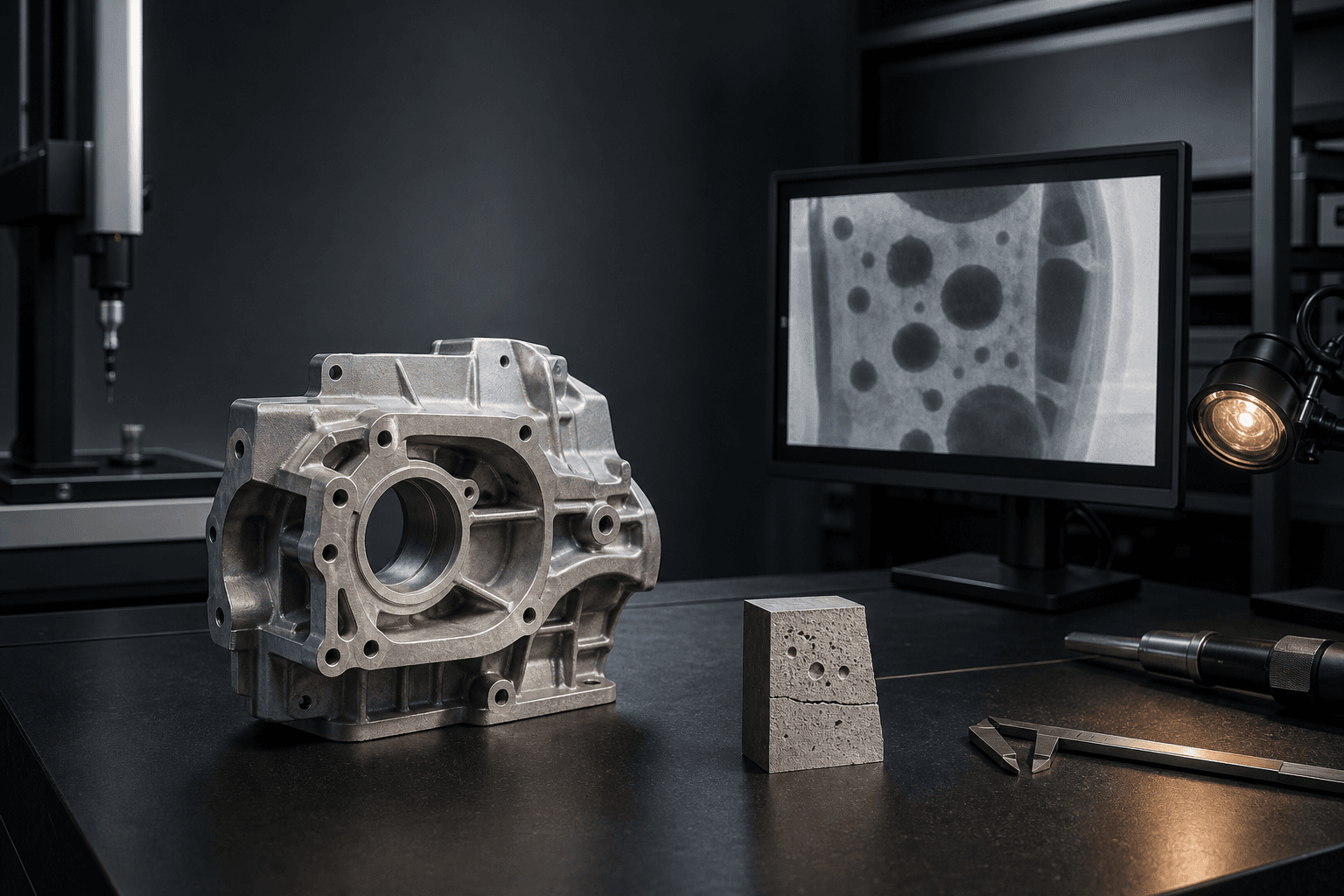
Magnesium alloy die-casting defects cannot be identified solely by surface appearance. Visually similar pores may originate from entrapped air, solidification shrinkage, or die lubricant decomposition; similarly, linear marks could be cold shuts, cracks, or die sticking-related pull marks. The correct approach is to correlate defect morphology, location, cross-sectional analysis, and process curves.
Key Diagnostic Summary
| Defect | Typical Characteristics | Priority Checks |
|---|---|---|
| Porosity | Smooth, rounded voids—often near flow convergence zones or exhaust ends | Exhaust design, vacuum level, spray volume, slow-to-fast shot transition |
| Cold Shut | Linear traces where two metal fronts fail to fuse properly | Gate location, fill time, molten metal & die temperature |
| Shrinkage Cavity | Irregular shape, commonly in thick sections or last-to-solidify areas | Wall thickness transitions, local intensification pressure, thermal balance & overflow design |
| Hot Tear | Extends along stress-concentrated regions with sharp, jagged edges | Fillet radii, ejection constraints, knockout timing, alloy selection & thermal processing window |
| Flash | Concentrated at parting lines, slides, or ejector pin locations | Clamping force, die wear, peak injection pressure & mating gap tolerances |
A Reproducible Diagnostic Workflow
Step 1: Freeze sample traceability data—die shot number, machine ID, cavity ID, material batch, shift, and post-casting processing status. Without full traceability, root-cause analysis quickly devolves into speculation.
Step 2: Confirm whether the defect exists as-cast—or emerges only after machining, blasting, baking, or coating. Die-cast surfaces are typically denser; subsurface voids exposed during machining do not indicate machining-induced defects.
Step 3: Use sectioning, metallography, X-ray, or CT scanning to verify the 3D morphology and spatial distribution of defects. Surface photos alone cannot reliably differentiate entrapped gas from shrinkage porosity.
Step 4: Overlay defect locations onto gate, overflow, exhaust, and thermal hotspot maps—then cross-reference vacuum curves, injection velocity profiles, intensification pressure, melt temperature, die temperature, and spray logs. Adjust only a few variables per iteration and retain pre-/post-change reference samples.
Why “Increasing Pressure” Often Fails
If turbulence-induced gas entrapment is the root cause, raising high-speed injection may worsen porosity; if cold shuts occur, the real issue may be excessive fill path length, insufficient die temperature, or mispositioned flow convergence—not pressure. For shrinkage cavities, focus must shift to last-to-solidify zones—not peak pressure alone. Parameter adjustments must align with the underlying defect mechanism.
What to Specify for Production Release
- Regional grading, dimensional limits, and quantity thresholds for surface defects;
- Internal quality requirements for critical load-bearing zones, sealing surfaces, and machined stock areas;
- Sampling frequency, detection sensitivity, and acceptance criteria for X-ray or CT inspection;
- Correlation rules linking leak rate, mechanical properties, and destructive sectioning results;
- Revalidation conditions triggered by die maintenance, parameter excursions, or material batch changes.
Frequently Asked Questions
Can impregnation fully resolve porosity?
No. Impregnation seals some interconnected micro-pores but cannot restore structural integrity lost due to weakened cross-sections—and must never replace root-cause control of gas entrapment or shrinkage.
Do cold shuts affect only aesthetics?
Not necessarily. When located in high-stress zones, near screw bosses, or on sealing surfaces, cold shuts can compromise fatigue life and hermeticity—requiring evaluation relative to both location and functional loading.
If you need technical support for defect root-cause analysis of your die-cast samples, contact us via Contact Us with defect photos, drawings, sectioning plans, and process records. Material grades and available forms are detailed in our Product Center.
Sources
ASTM E155 — Reference Radiographs for Inspection of Aluminum and Magnesium Castings ASM Handbook, Volume 15 — Casting