How to Achieve Thermal Balance in Magnesium Alloy Die-Casting Molds
Explains how mold temperature distribution, cooling circuit design, spray application, and cycle timing affect cold shuts, soldering, shrinkage porosity, and thermal fatigue—and outlines monitoring and maintenance methods for extending mold service life.
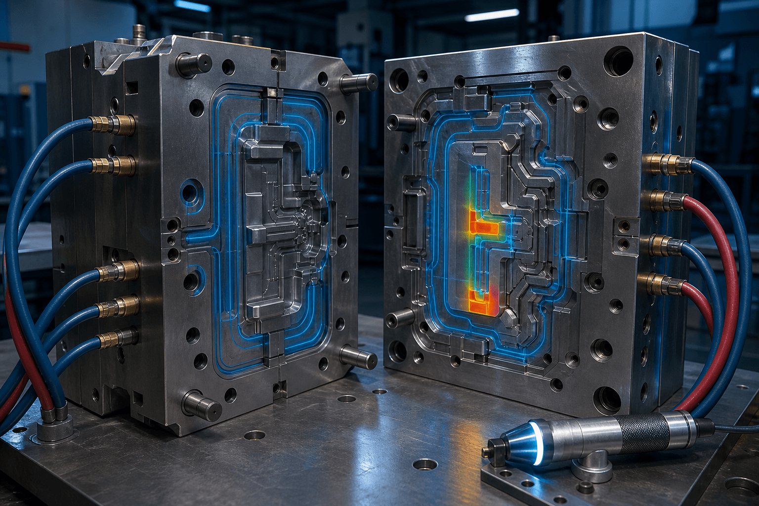
A die-casting mold’s ‘temperature compliance’ does not guarantee thermal balance. An average temperature reading may mask localized overheating near gates, excessive cooling in deep cavities, temperature differentials across slides, or uneven temperature recovery after downtime. Magnesium alloys fill rapidly and feature thin walls; even minor local temperature gradients can quickly manifest as cold shuts, soldering, part distortion, shrinkage porosity, or mold thermal fatigue.
Three Critical Aspects of Thermal Balance
First is spatial distribution: Different mold zones must operate within their respective process windows—not uniform temperature across the entire mold. Second is cycle-to-cycle stability: Temperature profiles during startup, short stops, and continuous production must be repeatable. Third is heat input/output balance: Heat introduced by molten metal, removed by spray cooling, conducted through the mold, and extracted via cooling circuits must all align precisely with cycle timing.
Common Temperature Anomalies and Their Consequences
| Anomaly | Possible Manifestations | Priority Checks |
|---|---|---|
| Overheating at gate or thick sections | Soldering, erosion, dimensional drift, thermal cracking | Localized cooling, gate velocity, spray parameters, material grade (e.g., AZ31B, ZK61) |
| Undercooling at flow fronts or thin walls | Cold shuts, flow marks, incomplete filling | Preheat temperature, cycle time, spray volume, gating & venting design |
| Left-right mold temperature imbalance | Warpage, uneven ejection, cavity mismatch | Circuit flow rates, blockages, slide contact integrity, scale buildup |
| Post-downtime temperature fluctuations | High scrap rate in first shots | Restart protocol, pre-heat cycles, first-piece quarantine |
Meaningful Mold Temperature Measurement
Handheld spot thermometers provide only isolated snapshots. A more robust approach combines fixed measurement points, standardized timing, and complementary technologies—embedded thermocouples, infrared thermal imaging, or coolant loop inlet/outlet temperature differentials. Measurement points should cover gates, thick thermal nodes, last-fill areas, slides, and locations historically prone to defects.
Mold Life Extends Beyond Cracking
Gate erosion, cavity corner collapse, ejector pin hole wear, vent clogging, parting-line indentation, and cooling channel scaling progressively degrade process consistency. Integrate shot count, repair history, critical dimensions, surface condition, coolant flow data, and defect trend analysis into a unified mold lifecycle record. Schedule preventive maintenance upon reaching predefined thresholds—far more controllable than emergency repairs after widespread flash or unplanned downtime.
Design & Maintenance Checklist
- Are cooling circuits positioned close to actual thermal nodes—and independently adjustable?
- Do circuits include flow, pressure differential, and leak monitoring?
- Do deep cavities, slender cores, and slides require high-conductivity inserts or dedicated cooling?
- Is spray application integrated into thermal balance strategy—not used merely as manual compensation?
- Are mold temperature and dimensional verification repeated after rework, polishing, or insert replacement?
- Are thermal cracks classified and managed by location, length, and propagation rate?
Does a Colder Mold Always Mean Faster Cycle Times?
No. Excessive cooling prolongs spray-water evaporation, increases cold shut risk, and disrupts cavity filling. The optimal target is stable, localized temperature windows—achieving the shortest qualified cycle time.
For assistance correlating mold temperature anomalies with defects, contact us via Contact Us with thermal images, cycle logs, and defect location maps. Candidate magnesium alloy grades are listed in our Product Center.
Sources
ASM Handbook, Volume 15 — Casting NADCA Die Materials Committee guidance