How to Design Gating Systems for Magnesium Alloy Die Casting: A Guide to In-Gates, Overflows, and Venting Validation
Explains how sprues, runners, in-gates, overflows, and venting systems work together in magnesium alloy die casting—and outlines a systematic gating and venting design methodology validated through mold flow analysis, short-shot trials, sectioning, and mass production.
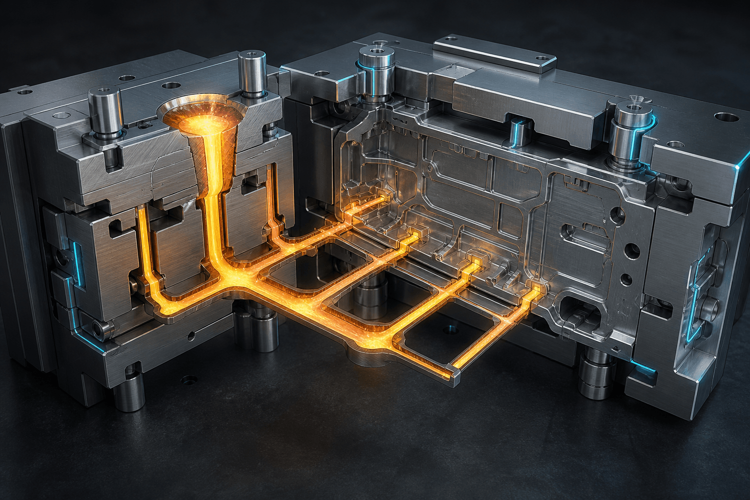
Designing gating systems for magnesium alloy die casting is far more than simply delivering molten metal into the cavity. It must precisely control flow direction, melt convergence location, air evacuation, thermal distribution, and pressure transmission—all within milliseconds. Runners, in-gates, overflows, and vents must be engineered as an integrated system; arbitrarily enlarging one component may simultaneously introduce new turbulence, cold shuts, or hot spots.
What Each Component Addresses
| Component | Primary Function | Typical Consequences of Poor Design |
|---|---|---|
| Runner | Distributes metal and stabilizes flow direction | Flow imbalance, premature convergence, excessive temperature drop |
| In-Gate | Controls velocity and direction of metal entering the cavity | Erosion, air entrapment, jetting, or incomplete filling |
| Overflow | Captures cold shot, oxide films, and end-of-fill metal | Defects retained in part zone, loss of control over last-fill location |
| Venting/Vacuum | Enables gas escape before cavity sealing | Porosity, vent clogging, abnormal vacuum curves |
Correct Design Sequence
First, define the desired fill direction based on part geometry, wall thickness, allowable gate locations, and post-machining zones. Next, allocate total gate area according to target fill time and machine capability. Then, direct the last-fill region toward removable overflows and venting zones. For multi-cavity molds or long-flow thin-walled parts, verify consistent arrival timing across all branches.
Mold flow analysis supports comparative evaluation—but should never substitute for physical validation. If material models, heat transfer coefficients, vent boundary conditions, or spray status deviate from shop-floor reality, even elegant flow-path simulations can mislead. Simulation results must be verified using short-shot samples, thermal imaging or temperature data, X-ray/CT scans, and defect-location mapping.
Why More Overflow Isn’t Always Better
Excessive overflow increases sprue weight, trimming load, and remelt volume—and may disrupt local thermal balance. Overflows should be placed only at actual last-fill locations and high-risk convergence zones, with documented evidence that they effectively divert cold metal and entrapped air away from the part. Vent cross-sectional area must balance exhaust capacity against risk of metal splash—and ensure cleanliness and service accessibility.
Pre-Mold-Release Review Checklist
- Does the gate feed from thick-to-thin sections—or advance stably per functional requirements?
- Is the convergence point of two melt fronts positioned away from high-stress, sealing, and cosmetic zones?
- Does the last-fill zone align precisely with overflow and vacuum valve locations?
- After trimming, are cracks, distortion, or unacceptable gate marks present?
- Will mold temperature, cooling circuit layout, and spray application alter the designed fill sequence?
- Are short-shot records, defect maps, and process curves preserved pre- and post-mold modification?
When porosity appears, can adding vents be the first step?
It’s a valid hypothesis—but first confirm whether porosity stems from air entrapment (not shrinkage or die lubricant decomposition); otherwise, additional vents may yield no improvement.
For expert review of your gating/venting or mold flow analysis, submit your 3D model, equipment specifications, and defect distribution via Contact Us. Material options are available in our Product Center.
Sources
https://doi.org/10.1016/S0924-0136(00)00546-X https://www.magnesiumtechnology.com/files/mgdiecasting.pdf