Why Do Magnesium Alloy Sheets Exhibit Directionality? Rolling Texture, Anisotropy, and Sampling Guidelines
Explains how the hexagonal crystal structure and rolling-induced texture cause directional variations in longitudinal, transverse, through-thickness, tensile, and compressive properties—and covers drawing notation, sampling, forming simulation, and batch acceptance.
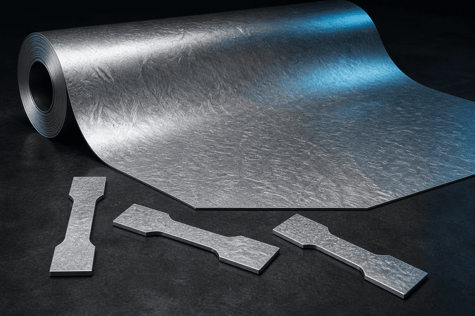
Magnesium alloy sheet cannot be represented by a single tensile strength and elongation value across all directions. Rolling induces crystallographic texture, and magnesium’s hexagonal close-packed (HCP) lattice exhibits highly direction-dependent slip and twinning systems—resulting in distinct mechanical responses along the longitudinal (L), transverse (T), 45° diagonal, through-thickness (C), and between tension and compression.
What Engineering Aspects Does Anisotropy Affect?
| Engineering Stage | Potential Impact |
|---|---|
| Structural Design | Yield strength, elongation, fatigue life, and notch sensitivity vary with orientation |
| Bending / Stamping | Crack initiation direction, minimum bend radius, springback, and earing height |
| Machining | Directional release of residual stresses and post-machining distortion |
| Incoming Material Inspection | Different test results from samples taken in different directions—even within the same batch |
| Failure Analysis | Correlation between crack propagation path and applied load direction |
Drawings Must Preserve Rolling Direction
If parts are nested from sheet stock, procurement drawings and nesting programs must explicitly indicate rolling direction. Suppliers may rotate nest layouts to improve material utilization—but doing so alters bending behavior, fatigue performance, or dimensional stability. For critical components, rolling direction should be designated as a special characteristic, with traceable markings retained on both remnants and finished parts.
How to Specify Sampling to Avoid Disputes
Material specifications typically define sampling location and orientation—but part-level validation requires additional longitudinal, transverse, or 45° specimens aligned with actual service loading. Bend testing must specify the relationship between bending axis and rolling direction; fatigue, compression, and fracture tests likewise require explicit directional definition. For thick plates, surface, mid-thickness, and through-thickness property gradients must also be assessed.
Simulation Must Not Assume Isotropic Behavior
When large deformations, high springback sensitivity, or multiaxial loading conditions apply, simplified isotropic material models may underestimate directional effects. Use stress–strain data matched to alloy grade, temper, thickness, and temperature—and calibrate models using real-part bending, deep-drawing, or forming limit tests.
Procurement & Production Checklist
- Alloy grade, temper, thickness, and rolling direction identification;
- Longitudinal, transverse, and required 45° mechanical properties;
- Sampling orientation for tensile, compression, bending, and fatigue testing;
- Change approval process for nesting rotation, flipping, or substitute material;
- Texture evolution and dimensional stability before/after heat treatment or leveling;
- Traceability between mill certificate data and actual plate sampling.
Does Rotating the Blank by 90° Always Cause Problems?
Not necessarily—but it changes the alignment between material direction and applied load/bending axis. Validation using either the target part or representative test coupons is mandatory; such rotation must not be treated as a neutral layout adjustment.
To develop a customized anisotropy-aware sampling plan, submit your loading conditions and nesting diagrams via Contact Us; available sheet options are listed in Products.
Sources
ASTM B90/B90M — Magnesium-Alloy Sheet and Plate ASM Handbook, Volume 14B — Sheet Forming