How to Design Threads and Inserts for Magnesium Alloys: Engagement Length, Torque, and Corrosion Protection Guide
Compares direct tapping, wire thread inserts, solid-threaded inserts, and die-cast embedded inserts for magnesium alloys—covering engagement length, stud design, torque control, loosening resistance, and galvanic corrosion validation.
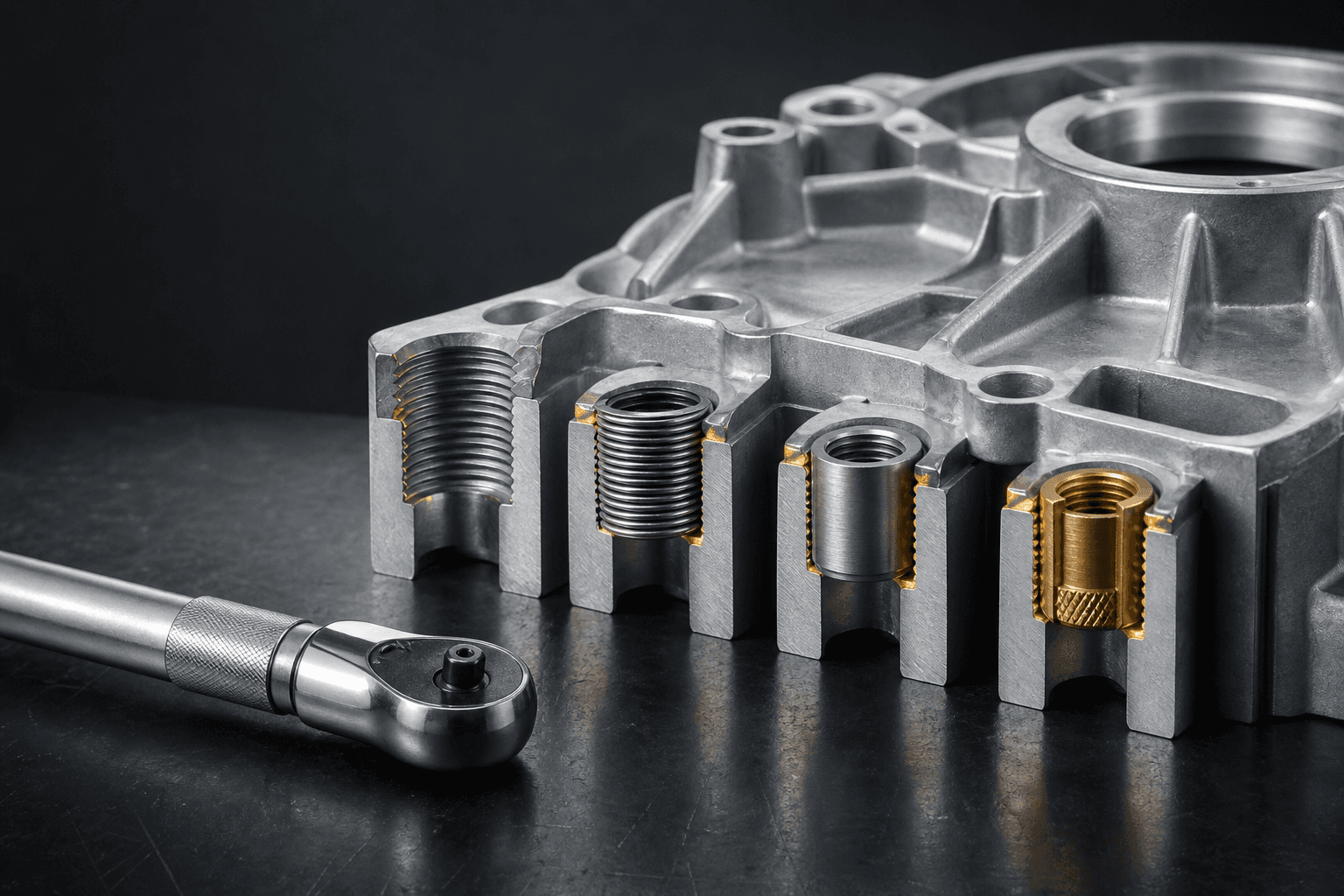
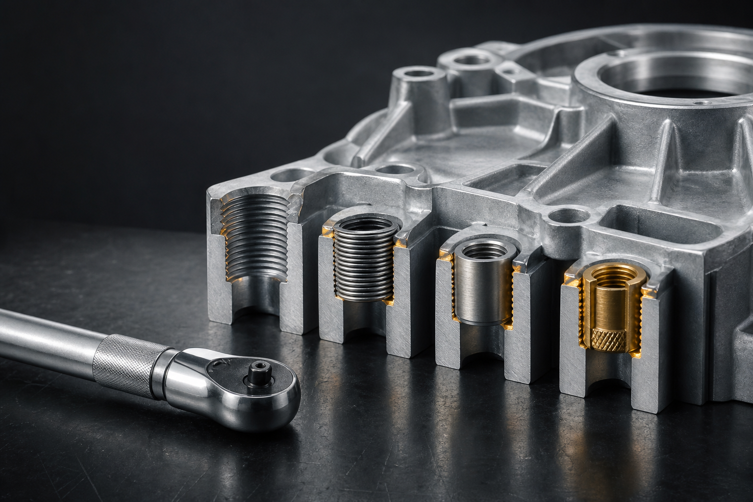
Magnesium alloys can be directly tapped or paired with wire thread inserts, solid-threaded inserts, or die-cast embedded inserts. The optimal solution depends on factors including repeated assembly/disassembly, clamping force, wall thickness, temperature, vibration, serviceability, and corrosive environment—not solely on single-use pull-out strength.
Four Common Approaches
| Approach | Advantages | Key Risks |
|---|---|---|
| Direct tapping into base material | Fewer parts, lower cost | Thread damage, repeated disassembly wear, localized bearing stress |
| Wire thread insert | Enhanced wear resistance and serviceability | Installation quality, tail protrusion, bore entry integrity, and galvanic corrosion |
| Solid-threaded insert | Higher load capacity and serviceability | Required hole diameter, minimum wall thickness, installation-induced stress, and added weight |
| Die-cast embedded insert | High integration, reduced post-processing | Insert positioning accuracy, metal flow dynamics, interfacial porosity, and thermal-cycle-induced loosening |
Engagement Length Cannot Be Determined by Steel-Based Rules of Thumb
Must be calculated based on base-material strength, bolt grade, pitch, effective number of engaged threads, and load direction—while accounting for bottom-hole clearance, chamfer geometry, and machining tolerances. To ensure failure occurs in the bolt rather than the magnesium thread, validate via pull-out or torque-to-failure testing—not by arbitrarily deepening the tapped hole.
Stud Design Determines Long-Term Durability
Stud root features must include adequate fillets and supporting ribs to prevent cracking under lateral loads or off-center assembly. For die-cast studs, mold filling, shrinkage cavity control, and ejection feasibility must also be considered; machined holes must avoid excessive penetration into internal porosity zones.
Torque Is Not the Sole Control Parameter
Identical torque values may yield significantly different clamp forces due to variations in friction coefficient. Coatings, lubricants, washers, and thread-locking compounds all influence friction. For critical joints, define an acceptable torque–clamp-force window via empirical testing—and monitor angle-of-turn, secondary locking, or breakaway torque.
Corrosion Protection Must Be Designed Into the Joint
Steel or copper-alloy inserts form galvanic couples with magnesium substrates in humid environments. Mitigation strategies include compatible plating, sealants, insulating washers, sealed bore entries, and drainage features—and corrosion performance must be validated under edge-cutting and assembly-induced scratching conditions.
Validation Checklist
- Single-cycle torque, pull-out, and over-torque failure testing;
- Thread condition after repeated assembly/disassembly;
- Clamp-force retention under vibration, thermal cycling, and creep;
- Joint resistance and strength after salt-spray or cyclic corrosion exposure;
- Insert installation depth, perpendicularity, and batch sampling inspection;
- Serviceability and field-proofing methods.
For evaluation of your magnesium-alloy joint design, submit bolt specifications, loading conditions, and environmental requirements via Contact Us. Compatible materials are listed in our Product Center.
Sources
VDI 2230 — Systematic Calculation of High Duty Bolted Joints ISO 16047 — Torque/Clamp Force Testing